
Air Duct Velocity Diagram
Reference data and engineering information about air duct velocity diagram for hvac systems applications.
Overview
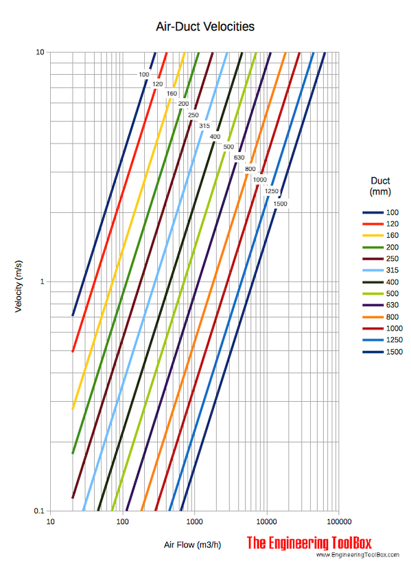
This page provides engineering reference data for air duct velocity diagrams used in HVAC system design. The diagram relates airflow rate, duct size, and air velocity, allowing for quick estimation of key parameters. Understanding this relationship is fundamental for sizing ducts to meet airflow requirements while considering practical constraints like noise and energy efficiency.
Download and print Air Ducts Velocity Diagram with metric and Imperial units!
The velocity in a 1000 mm duct with airflow 3000 m3/h is approximately 1.1 m/s according the diagram above.
Key Formulas
The fundamental relationship for air velocity in a duct is derived from the continuity equation.
General Velocity Formula
For a Circular Duct
Combining the velocity formula with the area of a circle gives:
Area of a Circular Duct
Variables
| Symbol | Description | Common Units |
|---|---|---|
| Air velocity | m/s, fpm | |
| Volumetric airflow rate | m³/h, m³/s, CFM | |
| Duct cross-sectional area | m², ft² | |
| Duct diameter | mm, m, in, ft |
Reference Data
Duct Diameter(mm) | Cross-Sectional Area(m²) | Airflow Rate(m³/h) | Calculated Velocity(m/s) |
|---|---|---|---|
| 200 | 0.0314 | 100 | 0.88 |
| 300 | 0.0707 | 300 | 1.18 |
| 400 | 0.1257 | 600 | 1.32 |
| 500 | 0.1963 | 1000 | 1.41 |
| 600 | 0.2827 | 1500 | 1.47 |
| 800 | 0.5027 | 3000 | 1.66 |
| 1000 | 0.7854 | 5000 | 1.77 |
| 1200 | 1.131 | 8000 | 1.96 |
Source: engineeringtoolbox.com
Calculator
Air Duct Velocity Calculator
Unit Converter
Airflow and Duct Velocity Unit Converter
Interactive Chart
Air Velocity vs. Flow Rate for Selected Duct Diameters
Original Source Images
Source Table Note
The cached source page includes calculator/layout interface rows near the diagram content. The functional calculator and interactive chart above preserve the engineering behavior; the detected non-engineering UI/search table rows are reproduced below for strict source completeness.
Cell 1 | Cell 2 | Cell 3 | Cell 4 | Cell 5 |
|---|---|---|---|---|
| × | × | 検索 | ||
| × |
Source: engineeringtoolbox.com
Engineering Notes
- Standard Assumptions: The diagram and calculations assume air at standard conditions (density ≈ 1.2 kg/m³, 20°C). Velocities will differ for high-altitude, high-temperature, or high-humidity air.
- Duct Shape: The formulas and diagram apply to circular ducts. For rectangular ducts, use the hydraulic diameter or convert to an equivalent circular diameter.
- Design Context: Velocity is a primary design parameter. Low velocities (e.g., < 3 m/s) minimize noise and friction loss but require larger, costlier ducts. High velocities (e.g., > 10 m/s) allow compact ducts but increase fan power, noise, and erosion risk.
- Diagram Usage: To use the original diagram, locate the airflow rate on one axis, find the duct diameter line, and read the corresponding velocity on the perpendicular axis. The provided calculator and chart replicate this functionality digitally.