
Bernoulli's Equation and Applications
Bernoulli's equation for fluid flow including venturi meters, pitot tubes and flow measurement.
Overview
The Bernoulli equation is a fundamental principle in fluid mechanics describing the conservation of energy for a steady, incompressible, and inviscid fluid flowing along a streamline. It relates the fluid's static pressure, kinetic energy per unit volume, and potential energy per unit volume.
Key Formulas
The Bernoulli equation states that the sum of the pressure energy, kinetic energy, and potential energy is constant along a streamline:
For comparing two distinct points (1 and 2) on the same streamline, the equation is written in its standard two-point form:
Energy Form
The original Engineering ToolBox page presents Bernoulli's equation as conservation of energy per unit mass:
where is energy per unit mass, is pressure, is fluid density, is velocity, is acceleration of gravity, is elevation, and is mechanical energy loss per unit mass. In Imperial calculations, remember that .
Head Form
Dividing by gravity gives Bernoulli's equation in head units:
with . A pressure head always depends on the density of the flowing fluid; for air velocity pressure, water-column values are usually calculated separately from the air density.
Dynamic Pressure
If elevation change and losses are negligible, Bernoulli's equation can be written in static plus dynamic pressure form:
The dynamic pressure is:
This is the basis for velocity measurement with pitot tubes and for pressure changes in venturi sections.
Variables
Symbol | Description | SI Unit |
|---|---|---|
| P | Static pressure | Pa |
| ρ | Fluid density | kg/m³ |
| v | Flow velocity | m/s |
| g | Gravitational acceleration | m/s² |
| h | Elevation above a reference plane | m |
Source: engineeringtoolbox.com
Calculator
Bernoulli Equation (Point 2 Pressure)
Dynamic Pressure Calculator
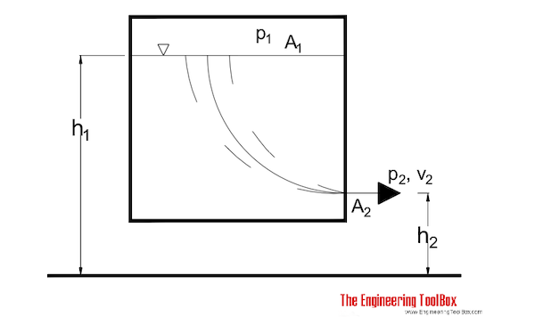
Discharge from a Pressure Vessel
For flow from a tank or pressure vessel through an outlet, the original page rearranges Bernoulli's equation to estimate outlet velocity:
For a vented tank with a large free surface, is small and , so the expression reduces to Torricelli's equation:
With a discharge coefficient , the practical outlet velocity is:
For a pressurized vessel where liquid level is negligible compared with pressure difference:
Tank or Pressure Vessel Outlet Velocity
Energy Loss through a Reduction Valve
If velocity and elevation changes are small across a throttling valve, the mechanical energy loss per unit mass is:
Reduction Valve Energy Loss
Unit Converter
Bernoulli Pressure and Head Unit Converter
Restored Original Source Tables
The original source page includes table markup around shared site controls such as search boxes and layout rows, but it does not contain a separate engineering data table for this article. The complete engineering content from those sections is represented above as formulas, explanatory text, calculators, and preserved source images.
Source cell 1 | Source cell 2 | Source cell 3 | Source cell 4 | Source cell 5 |
|---|---|---|---|---|
| × | × | 検索 | ||
| × |
Source: engineeringtoolbox.com
Original Source Images
The following original source images are preserved to avoid losing visual reference material. When an image contains chart or tabular data, its extracted values are represented in the page tables, calculators, or interactive charts; remaining images are retained as visual source references.
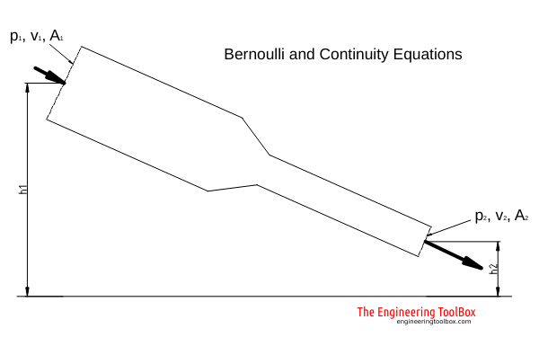 Bernoulli Equation
Interactive Bernoulli Diagram Data
Bernoulli Energy Terms Along a Streamline
Flow Out of Tank Example - Torricelli Velocity
Engineering Notes
- Idealizations: The standard equation assumes steady, incompressible, inviscid flow along a streamline. Real fluids experience viscous losses (friction), requiring an extended form that includes a head loss term.
- Compressibility: For flows where the Mach number exceeds approximately 0.3 (Ma > 0.3), compressibility effects become significant, and the incompressible Bernoulli equation is invalid.
- Applications & Caveats: While the principle explains phenomena like lift generation and the Venturi effect, it cannot be applied across streamlines or through machines like pumps or turbines without adding or removing energy.
- Pipe Flow: In practical engineering for pipe systems, the Bernoulli equation is typically combined with the Darcy-Weisbach equation to account for frictional head loss.