
Capacitors Energy Power
Reference data and engineering information about capacitors energy power for electrical applications.
Overview
Capacitors store energy in an electric field between their plates. The stored energy and the power available during discharge are fundamental to designing timing circuits, power supplies, and energy storage systems. This page covers the core formulas for energy storage, instantaneous power delivery, and discharge time under constant-power loading.
Key Formulas
Energy Stored in a Capacitor
Where W is the energy stored (joules), C is capacitance (farads), and V is the voltage across the capacitor (volts).
Average Power During Discharge
This gives the average power over a discharge pulse of duration t. In practice, discharge starts at a peak and decays, so this is a rough engineering estimate rather than a constant instantaneous value.
Discharge Time at Constant Power Load
Rearranging the power equation gives the time required to fully discharge a capacitor into a load that consumes power P at a constant rate.
Variables
| Symbol | Description | Unit |
|---|---|---|
| Energy stored (work done) | J | |
| Capacitance | F | |
| Voltage across capacitor | V | |
| Power | W | |
| Discharge time | s |
Example Calculation
A 10 µF capacitor is charged to 230 V.
Stored energy:
Average power if discharged in 5 µs:
Capacitor Energy and Power
Capacitor Discharge Time at Constant Power
Unit Converter
Capacitance, Energy, and Power Unit Converter
Original Source Images
The following original source images are preserved to avoid losing visual reference material. When an image contains chart or tabular data, its extracted values are represented in the page tables, calculators, or interactive charts; remaining images are retained as visual source references.
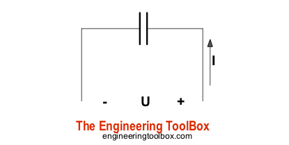 Capacitor
Source Table Coverage
The cached source includes Engineering ToolBox layout/search rows around the calculator area. The substantive migrated content is preserved as the capacitor energy calculator, dielectric breakdown table, original capacitor image, and the unit converter above.
Source cell 1 | Source cell 2 | Source cell 3 | Source cell 4 | Source cell 5 |
|---|---|---|---|---|
| × | × | 検索 | ||
| × |
Source: engineeringtoolbox.com
Engineering Notes
- Exponential decay: In a resistive-load circuit, voltage (and therefore instantaneous power) decays exponentially — not linearly. The formula yields a rough average over the pulse duration, not the peak.
- Peak power is higher: At the start of discharge the instantaneous power is (for a resistive load), which can far exceed the average value.
- ESR limits: Real capacitors have equivalent series resistance (ESR) that limits peak current and converts some energy to heat inside the component rather than the load.
- Safe design margin: Always derate the working voltage well below the dielectric breakdown value, accounting for temperature, aging, and transient overvoltage.
Breakdown Voltage by Dielectric
Puncture voltage measured at 1 MHz. Values in V per mil (1 mil = 0.001 inch ≈ 25.4 µm).
This dielectric breakdown table is retained as source-related capacitor design reference material needed for completeness of the migrated capacitor page; it supports the voltage derating and safe working-voltage notes above.
Material | Breakdown(V/mil) |
|---|---|
| Air | 240 |
| Alsimag | 240 |
| Bakelite | 300 |
| Bakelite, mica-filled | 325 – 375 |
| Cellulose acetate | 250 – 600 |
| Formica | 450 |
| Glass, window | 200 – 250 |
| Glass, Pyrex | 335 |
| Mica, ruby | 3800 – 5600 |
| Plexiglas | 990 |
| Polyethylene | 1200 |
| Polystyrene | 500 – 700 |
| Porcelain | 40 – 100 |
| Quartz, fused | 1000 |
| Steatite, low-loss | 150 – 315 |
| Teflon | 1000 – 2000 |
Source: engineeringtoolbox.com
Actual breakdown depends on temperature, frequency, dielectric thickness, and electrode geometry. Consult manufacturer datasheets for rated working voltages.