
Electrical Formulas
Reference data and engineering information about electrical formulas for electrical applications.
Overview
Fundamental formulas for DC and single-phase and three-phase AC electrical circuits, covering Ohm's Law, power, impedance, and motor calculations.
Key Formulas
Ohm's Law
The relationship between voltage, current, and resistance in any electrical circuit.
DC Power
Energy
where t is time in seconds (J) or hours (Wh).
AC Single-Phase Power
AC Three-Phase Power
Impedance (Series RLC)
Inductive Reactance
Capacitive Reactance
Variables
Symbol | Description | Unit |
|---|---|---|
| V | Voltage (potential difference) | V |
| I | Current | A |
| R | Resistance | Ω |
| P | Real power | W |
| W | Energy | J or Wh |
| Z | Impedance | Ω |
| f | Frequency | Hz |
| L | Inductance | H |
| C | Capacitance | F |
| cos φ | Power factor | — |
Source: engineeringtoolbox.com
Electrical Units
Unit | Symbol | Definition |
|---|---|---|
| Volt | V | Potential required to push 1 A through 1 Ω of resistance |
| Ohm | Ω | Resistance that limits 1 A when driven by 1 V |
| Ampere | A | Current driven through 1 Ω by 1 V |
| Watt | W | Product of 1 A and 1 V; unit of real power |
| Volt Ampere | VA | Product of V and A readings; equals watts in DC; may exceed watts in AC due to reactive component |
| kiloVolt Ampere | kVA | 1 000 volt amperes |
| Power Factor | PF | Ratio of real power (W) to apparent power (VA) |
Source: engineeringtoolbox.com
Calculators
Ohm's Law
Ohm's Law
DC Power & Energy
Power and Energy
Unit Converter
The source page included a Unit Converter section. This calculator preserves common electrical unit conversions used with the formulas above.
Electrical Unit Converter
Motor Formulas
For three-phase AC motors the following relationships apply.
Motor Efficiency
where P_hp is shaft horsepower and P_in is electrical input in watts.
For a three-phase supply:
Motor Current (3-Phase)
Motor Input Power (3-Phase)
Worked Examples
Battery & resistor — A 12 V battery drives an 18 Ω load:
Resistor dissipation — 12 V across 50 Ω for 60 s:
Stove — 5 MJ consumed from 230 V in 60 min:
Interactive Ohm's Law Charts
The source page includes Ohm's Law and power nomogram images. The charts below convert their relationships into interactive datasets.
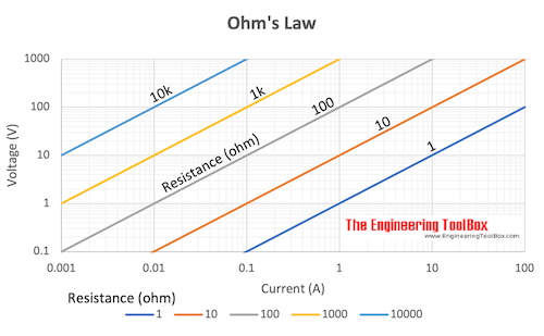
Ohm's Law - Voltage vs Current and Resistance
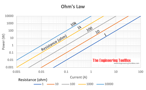
Ohm's Law - Power vs Current and Resistance
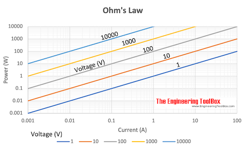
Ohm's Law - Power vs Current and Voltage
Restored Original Source Tables
The following tables are restored from the original source page to preserve the complete reference data.
Original Source Images
The following original source images are preserved to avoid losing visual reference material. When an image contains chart or tabular data, its extracted values are represented in the page tables, calculators, or interactive charts; remaining images are retained as visual source references.
 ohms law
Engineering Notes
- DC vs. AC power: In DC circuits volt-amperes equal watts. In AC circuits the power factor causes apparent power (VA) to exceed real power (W). Always specify whether a rating is in W or VA.
- Power factor correction: Industrial facilities often install capacitor banks to bring the power factor closer to unity, reducing demand charges and line losses.
- Three-phase convention: The √3 factor assumes a balanced three-phase system. Unbalanced loads require per-phase analysis.
- Motor efficiency (η): The constant 746 converts horsepower to watts (1 hp = 746 W). Typical motor efficiencies range from 80 % to 96 % depending on size and class.
- Thermal limits: Formulas assume steady-state conditions. Actual conductor and component ratings must account for ambient temperature, insulation class, and duty cycle per NEC / IEC standards.
- Reactive power: Inductive and capacitive reactance cause current and voltage to be out of phase. The impedance formula combines resistive and reactive components in series.