
Electrical Resistor Colour Code Value Tolerance
Reference data and engineering information about electrical resistor colour code value tolerance for electrical applications.
Overview
Engineering ToolBox - Resources, Tools and Basic Information for Engineering and Design of Technical Applications!
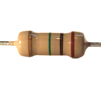
The resistor color code is an international standard for marking the resistance value and tolerance of axial-lead through-hole resistors. Each colored band on the resistor body encodes a digit, multiplier, or tolerance specification. This system enables quick identification without requiring measurement instruments.
Resistors use either four bands (standard tolerance) or five bands (precision tolerance). The first band is always located nearest one end of the resistor body.
Download and print Resistors - Standard Colors Codes table.
Key Formulas
Four-Band Resistance Value
where and are the first two significant digits and is the multiplier exponent.
Five-Band Resistance Value
where , , and are the first three significant digits and is the multiplier exponent.
Actual Resistance Range
Variables
| Symbol | Description | Unit |
|---|---|---|
| Nominal resistance | Ω | |
| Significant digit from color band | — | |
| Multiplier exponent from color band | — | |
| Actual resistance within tolerance | Ω |
Color Code Reference
Color | Significant Digit | Multiplier | Tolerance |
|---|---|---|---|
| Black | 0 | ×1 | — |
| Brown | 1 | ×10 | ±1% |
| Red | 2 | ×100 | ±2% |
| Orange | 3 | ×1 k | — |
| Yellow | 4 | ×10 k | — |
| Green | 5 | ×100 k | ±0.5% |
| Blue | 6 | ×1 M | ±0.25% |
| Violet | 7 | ×10 M | ±0.1% |
| Grey | 8 | ×100 M | — |
| White | 9 | ×1 G | — |
| Gold | — | ×0.1 | ±5% |
| Silver | — | ×0.01 | ±10% |
| None | — | — | ±20% |
Source: engineeringtoolbox.com
Interactive Standard Color Code Chart
The original resistors_standard_color_codes.png image is represented below as numeric color-code data. The multiplier value is shown as a base-10 exponent so gold and silver can be included with the standard digit colors.
Resistors - Standard Color Codes
How to Read Resistor Bands
Four-Band Resistors
- Band 1 — First significant digit.
- Band 2 — Second significant digit.
- Band 3 — Multiplier (power of ten).
- Band 4 — Tolerance (gold = ±5%, silver = ±10%, none = ±20%).
Example: Yellow, Violet, Orange, Red → with ±2% tolerance.
Five-Band Resistors
- Band 1 — First significant digit.
- Band 2 — Second significant digit.
- Band 3 — Third significant digit.
- Band 4 — Multiplier.
- Band 5 — Tolerance (brown = ±1%, red = ±2%).
Example: Red, Yellow, White, Orange, Brown → with ±1% tolerance.
Calculator
Four-Band Resistance Calculator
Five-Band Resistance Calculator
Unit Converter
Electrical Resistance Unit Converter
Restored Original Source Tables
The following tables are restored from the original source page to preserve the complete reference data.
Resistors - Color Codes
Color | Significant Figures | Multiplier | Tolerance |
|---|---|---|---|
| Silver | 10^-2 | +/- 10% | |
| Gold | 10^-1 | +/- 5% | |
| Black | 0 | 1 | |
| Brown | 1 | 10 | +/- 1% |
| Red | 2 | 10^2 | +/- 2% |
| Orange | 3 | 10^3 | |
| Yellow | 4 | 10^4 | |
| Green | 5 | 10^5 | +/- 0.5% |
| Blue | 6 | 10^6 | +/- 0.25% |
| Violet | 7 | 10^7 | +/- 0.1% |
| Grey | 8 | 10^8 | |
| White | 9 | 10^9 | |
| None | +/- 20% |
Source: engineeringtoolbox.com
Download and print Resistors - Standard Colors Codes table.
Four Band Resistor Calculator
None Brown Red Orange Yellow Green Blue Violet Gray White | None Black Brown Red Orange Yellow Green Blue Violet Gray White | None Black Brown Red Orange Yellow Green Blue Gold Silver | None Brown Red Gold Silver |
|---|---|---|---|
| Band 1 options: None, Brown, Red, Orange, Yellow, Green, Blue, Violet, Gray, White | Band 2 options: None, Black, Brown, Red, Orange, Yellow, Green, Blue, Violet, Gray, White | Multiplier options: None, Black, Brown, Red, Orange, Yellow, Green, Blue, Gold, Silver | Tolerance options: None, Brown, Red, Gold, Silver |
| 47 kOhm +/- 2% | 47 kOhm +/- 2% | 47 kOhm +/- 2% | 47 kOhm +/- 2% |
Source: engineeringtoolbox.com
Five Band Resistor Calculator
None Brown Red Orange Yellow Green Blue Violet Gray White | None Black Brown Red Orange Yellow Green Blue Violet Gray White | None Black Brown Red Orange Yellow Green Blue Violet Gray White | None Black Brown Red Orange Yellow Green Blue Gold Silver | None Brown Red Gold Silver |
|---|---|---|---|---|
| Band 1 options: None, Brown, Red, Orange, Yellow, Green, Blue, Violet, Gray, White | Band 2 options: None, Black, Brown, Red, Orange, Yellow, Green, Blue, Violet, Gray, White | Band 3 options: None, Black, Brown, Red, Orange, Yellow, Green, Blue, Violet, Gray, White | Multiplier options: None, Black, Brown, Red, Orange, Yellow, Green, Blue, Gold, Silver | Tolerance options: None, Brown, Red, Gold, Silver |
| 249 kOhm +/- 1% | 249 kOhm +/- 1% | 249 kOhm +/- 1% | 249 kOhm +/- 1% | 249 kOhm +/- 1% |
Source: engineeringtoolbox.com
Original Source Images
The following original source images are preserved to avoid losing visual reference material. When an image contains chart or tabular data, its extracted values are represented in the page tables, calculators, or interactive charts; remaining images are retained as visual source references.

Engineering Notes
- Reading direction: If the resistor has a gold or silver band, that band is always the tolerance band and should be read from the opposite end. When no metallic band is present, read from the end closest to the first band.
- Temperature coefficient: A sixth band (rare) indicates the temperature coefficient in ppm/°C, typically using the same color-to-digit mapping.
- Surface-mount devices (SMD): Modern chip resistors use a printed numerical code (e.g., "473" = 47 × 10³ = 47 kΩ) or the EIA-96 marking system rather than color bands.
- Standard values: Resistors follow the E-series (E12, E24, E48, E96, E192) preferred-value grids. Not every arbitrary resistance is manufactured; available values follow logarithmic spacing within each decade.
- Tolerance stacking: When combining resistors in series or parallel, the resulting tolerance is generally tighter than individual tolerances due to statistical averaging, but worst-case analysis should use simple addition of absolute deviations.