Equivalent Pipe Length Method
Reference data and engineering information about equivalent pipe length method for fluid mechanics applications.
Overview
The Equivalent Pipe Length Method simplifies pressure-loss calculations in piping networks by converting every valve, fitting, and component into an equivalent length of straight pipe. Once all losses are expressed in the same unit, total pressure drop along any flow path is found by simple addition — making it straightforward to identify the critical path and size both the pump and any required balancing valves.
This approach works well for closed-loop hydronic heating, chilled-water distribution, domestic water supply, and similar systems where pipe sizes within each branch are consistent.
Key Formulas
Darcy-Weisbach Pressure Drop
Friction pressure loss along a pipe section, where is the total equivalent length (actual pipe + fittings expressed as equivalent pipe length).
Equivalent Length of a Fitting
Each fitting has a characteristic ratio. Multiply by the actual internal pipe diameter to get the equivalent straight-pipe length.
Total Section Equivalent Length
Hazen-Williams (Alternative)
Empirical formula popular in water-supply design ( in psi, in ft, in gpm, in inches).
Variables
| Symbol | Description | Unit |
|---|---|---|
| Pressure drop | Pa | |
| Darcy friction factor | — | |
| Equivalent length | m | |
| Internal pipe diameter | m | |
| Fluid density | kg/m³ | |
| Mean flow velocity | m/s | |
| Hazen-Williams roughness coefficient | — | |
| Volumetric flow rate | m³/s or gpm |
Step-by-Step Procedure
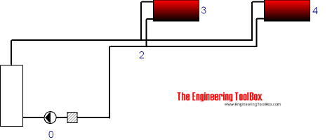
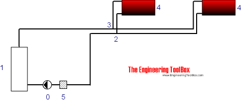
- Draw a node diagram — Assign a node to each junction (tees, pumps, radiators). Simplify where supply and return pipes share the same diameter.
- Build a calculation table — One row per pipe section (node-to-node). Columns for: section ID, pipe length, volume flow, pipe size, friction pressure loss per unit length, and equivalent length of fittings.
- Enter pipe data — Look up or calculate pressure-loss-per-unit-length for each section from manufacturer tables, or compute via Darcy-Weisbach / Hazen-Williams.
- Convert fittings — Use published ratios (see table below) to express every valve and fitting as an equivalent length of straight pipe. Add to the actual pipe length.
- Total each section — Multiply total equivalent length by the per-unit-length pressure drop.
- Sum each unique path — From the pump (node 0) through every branch to the return point. The highest total sets the required pump head.
- Add balancing valves — In branches with lower path losses, install balancing valves sized to absorb the pressure difference and equalise flow.
Typical Equivalent Lengths (L/D Ratios)
Fitting / Component | L/D Ratio | Notes |
|---|---|---|
| Gate valve (fully open) | 8 | Low restriction |
| Globe valve (fully open) | 340 | High restriction |
| Butterfly valve (fully open) | 35 | |
| Check valve — swing | 50 | |
| Check valve — lift | 600 | Very high loss |
| Ball valve (fully open) | 3 | Low restriction |
| 90° elbow (standard) | 30 | r/D ≈ 1.0 |
| 90° elbow (long radius) | 20 | r/D ≈ 1.5 |
| 45° elbow | 16 | |
| Tee — run (straight through) | 20 | |
| Tee — branch (90°) | 60 | |
| Coupling / union | 2 | |
| Entrance (sharp-edged) | 30 | Approximate |
| Exit | 20 | Approximate |
Source: engineeringtoolbox.com
To convert an L/D ratio to equivalent length for a specific pipe: .
Equivalent Length Calculator
Section Equivalent Length & Pressure Drop
The calculator uses for 90° elbows and for gate valves by default. Adjust your actual counts accordingly.
Unit Converter
Equivalent Pipe Length Unit Converter
Design Notes
- Unit consistency is critical. Mixing Imperial and SI values (e.g., gpm with metres) is the most common source of error. Verify that your pipe-loss data matches your flow and dimension units before summing.
- The critical-path concept — always sum every possible pump-to-return path and use the largest total as the design pump head. Missing a path leads to under-sizing.
- Balancing valve placement — a balancing valve should be installed in the branch with the lowest path loss. Its pressure-drop rating must equal the difference between that branch and the critical path.
- Turbulent flow assumption — published L/D ratios assume fully turbulent (high Reynolds number) flow. At very low velocities in large pipes the regime may be transitional, and fitting losses will differ.
- Pipe roughness ages. New C-factor or friction-factor values apply to clean pipe. In aging systems, internal scaling increases friction; design with a safety margin.
- Applicability — the method works for hot-water heating, chilled-water loops, gravity-fed circuits, potable water distribution, and similar closed- or open-loop hydronic systems.
Restored Original Source Tables
The following tables are restored from the original source page to preserve the complete reference data.
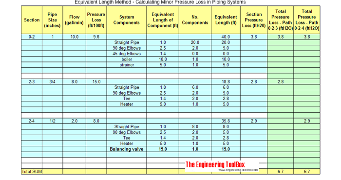
The original page's primary calculation table is embedded in the equivalent-pipe-length-method.png image and is preserved in the image section below. Its two example flow paths are represented explicitly here so the migrated page keeps the source table logic in structured form.
Example path | Sections included | Migration handling |
|---|---|---|
| Path 1 | 0 - 2 - 3 | Preserved from the source calculation-table example and represented in the interactive diagram data below. |
| Path 2 | 0 - 2 - 4 | Preserved from the source calculation-table example and represented in the interactive diagram data below. |
Source: engineeringtoolbox.com
Original Source Images
The following original source images are preserved to avoid losing visual reference material. When an image contains chart or tabular data, its extracted values are represented in the page tables, calculators, or interactive charts; remaining images are retained as visual source references.