
Heat Loss Buildings
Reference data and engineering information about heat loss buildings for thermodynamics applications.
Overview
Heat loss through building envelopes is driven by the temperature difference between indoor and outdoor environments and the thermal resistance of each assembly layer. By summing the resistances of all material layers plus interior and exterior surface films, designers estimate steady-state heat flow (in watts) through walls, roofs, floors, and ground-contact elements. The reference values below apply to approximate calculations for common construction types.
Key Formulas
Steady-State Heat Loss Through a Building Component
Total Thermal Resistance (Series Layers)
For earth-contact assemblies, replace the exterior air film resistance with the equivalent ground resistance from the table below.
Overall Heat Transfer Coefficient
So the heat loss can also be written as:
Variables
| Symbol | Description | Unit |
|---|---|---|
| Heat loss rate | W | |
| Area of building component | m² | |
| Indoor-outdoor temperature difference | K or °C | |
| Total thermal resistance | m²K/W | |
| Interior surface film resistance | m²K/W | |
| Exterior surface film resistance | m²K/W | |
| Equivalent resistance for earth-contact elements | m²K/W | |
| Overall heat transfer coefficient | W/m²K | |
| Basement floor level below earth bound | m |
Thermal Resistance Data
Inside and Outside Surface Films
Building Parts | Ri (Inside)(m^2K/W) | Ro (Outside)(m^2K/W) | Ri + Ro(m^2K/W) |
|---|---|---|---|
| Parts against the surrounding environment | 0.13 | 0.04 | 0.17 |
| Other building parts (interior partitions) | 0.13 | 0.13 | 0.26 |
Source: engineeringtoolbox.com
Building Elements Against Earth
Description | Re(m^2K/W) |
|---|---|
| Floors 0.5 m above to 0.5 m below earth, 0-1 m from exterior wall, no cold bridge protection | 0.2 |
| Floors 0.5 m above to 0.5 m below earth, with cold bridge protection | 1.0 |
| Center-field floor, above 1 m from exterior wall | 1.5 |
| Basement floor 0.5 m below earth bound | 2.0 |
| Basement walls below earth, full wall against soil | 0.2 + 0.3h |
| Basement walls below earth, floor partly against air | 2.0 |
Source: engineeringtoolbox.com
Calculator
Steady-State Building Heat Loss
Unit Converter
Building Heat Loss Unit Converter
Interactive Ground Heat Loss Diagram
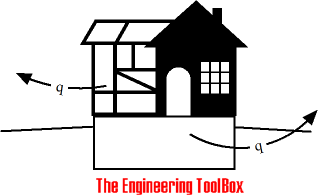
The original building_heat_loss_ground.png diagram is represented below using the restored earth-contact resistance data. The chart shows how equivalent ground resistance changes for common floor and basement-wall conditions.
Building Heat Loss Through Ground - Equivalent Resistance
Restored Original Source Tables
The following tables are restored from the original source page to preserve the complete reference data.
Thermal Resistance - Inside and Outside Walls
Ri = 1/fi 1) | Ro = 1/fo 1) | Ri+ Ro | Resistance (m2K/W) |
|---|---|---|---|
| Building parts against the surrounding environment | 0.13 | 0.04 | 0.17 |
| Building parts others | 0.13 | 0.13 | 0.26 |
Source: engineeringtoolbox.com
Building Elements - Thermal Resistance against Earth
Re | Resistance (m2K/W) |
|---|---|
| Floors 0.5 m above to 0.5 below earth bound, 0-1 m from inside outside wall - without cold bridge protection | 0.2 |
| Floors 0.5 m above to 0.5 below earth bound - with cold bridge protection | 1 |
| Center-field above 1 m from inside outside wall | 1.5 |
| Basement floors 0.5 m below earth bound | 2 |
| Basement walls under earth bound, the whole wall against the earth, where h is the basement floors level below the earth bound (m) | 0.2 + 0.3 h |
| Basement walls under earth bound, basement floor against the earth and partly against air | 2 |
Source: engineeringtoolbox.com
Original Source Images
The following original source images are preserved to avoid losing visual reference material. When an image contains chart or tabular data, its extracted values are represented in the page tables, calculators, or interactive charts; remaining images are retained as visual source references.
Engineering Notes
- Steady-state assumption. The formula assumes constant indoor and outdoor temperatures. Real conditions involve daily and seasonal cycles, solar gains, and internal heat sources that make dynamic analysis more accurate for energy modeling.
- Thermal bridges. Structural connections (steel studs, slab edges, lintels) create localized paths of low resistance not captured by simple layer-by-layer R-value sums. Cold bridge protection values in the earth-contact table account for some of this, but detailed projects require thermal bridge calculations (ψ-values).
- Ground-contact resistance depends on geometry. The values for earth-contact elements are simplified equivalents. Actual heat loss depends on soil conductivity, moisture content, depth, and the ratio of wall height to floor width. The expression increases resistance with depth because deeper soil temperatures are more stable.
- Interior surface film ( m²K/W) corresponds roughly to a still-air film with a heat transfer coefficient of about W/m²K. The exterior film ( m²K/W) reflects wind-exposed conditions ( W/m²K). Values vary with surface orientation and emissivity.
- Total resistance includes all layers. When using the tables above, add the (or ) surface values to the resistances of the wall, insulation, and cladding layers to get .
- Units. Resistance is in m²K/W. A higher R-value means better insulation. The U-value () has units of W/m²K, where lower is better.