
Linear Thermal Expansion
Reference data and engineering information about linear thermal expansion for thermodynamics applications.
Overview
When a solid material is heated or cooled, its dimensions change proportionally to the original size and the temperature change. This predictable behavior is critical for designing joints, clearances, piping systems, and structures that experience temperature variations in service.
Linear thermal expansion applies to one-dimensional length changes. Related quantities include superficial expansion (area change, coefficient ≈ 2α) and cubic expansion (volume change, coefficient ≈ 3α).
Key Formulas
Change in Length
Final Length
Superficial (Area) Expansion
Cubic (Volumetric) Expansion
Variables
| Symbol | Description | Unit |
|---|---|---|
| Change in length | m | |
| Original length | m | |
| Final length | m | |
| Linear expansion coefficient | m/m·°C | |
| Superficial expansion coefficient | m²/m²·°C | |
| Cubic expansion coefficient | m³/m³·°C | |
| Temperature change () | °C or K |
Common Linear Expansion Coefficients
Material | Coefficient α(10⁻⁶ /°C) |
|---|---|
| Aluminum | 23 |
| Brass | 19 |
| Bronze | 18 |
| Carbon steel | 12 |
| Copper | 17 |
| Glass (soda-lime) | 8.5 |
| Invar (Fe-36Ni) | 1.2 |
| Iron (cast) | 10.8 |
| PVC | 52 |
| Stainless steel (304) | 17.3 |
| Titanium | 8.6 |
| Wood (along grain) | 5 |
Source: engineeringtoolbox.com
Thermal Expansion Calculator
Linear Thermal Expansion Calculator
Unit Converter
The source page included a Unit Converter section. This migrated converter covers the units normally used with thermal expansion calculations: length, expansion movement, temperature difference, and expansion coefficient.
Thermal Expansion Unit Converter
Expansion Example
An aluminum beam ( /°C) is 6 m long when assembled at 20 °C. For a design range of −30 °C to 50 °C:
At −30 °C:
At +50 °C:
The beam length varies by approximately 11 mm across the full design range.
Original Source Images
The following original source images are preserved to avoid losing visual reference material. When an image contains chart or tabular data, its extracted values are represented in the page tables, calculators, or interactive charts; remaining images are retained as visual source references.
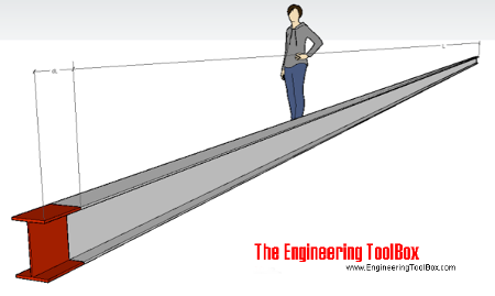
Interactive Aluminum Beam Expansion Data
The original aluminum-beam diagram is represented below with the same example basis: a 6 m aluminum beam assembled at 20 °C with /°C.
Aluminum Beam Thermal Expansion
Engineering Notes
- Temperature dependence of α: Expansion coefficients are not strictly constant. For wide temperature ranges, use segment-wise calculation with coefficients valid for each sub-range, or integrate if available.
- Differential expansion: In assemblies with dissimilar materials, the difference in expansion coefficients governs interface stresses and required clearances. Invar and similar low-expansion alloys are used where dimensional stability is critical.
- Constraints matter: The formulas above assume free expansion. If a member is restrained, thermal stresses develop instead: , where is the elastic modulus.
- Superficial and cubic coefficients: For isotropic materials, and are accurate approximations. For anisotropic materials (e.g., wood, composites), expansion differs by direction.
- Practical gaps and clearances: Expansion joints, sliding supports, and flexible couplings must accommodate the full range of with adequate safety margin.