
Steel Pipe Weights
Reference data and engineering information about steel pipe weights for material properties applications.
Overview
Engineering ToolBox - Resources, Tools and Basic Information for Engineering and Design of Technical Applications!
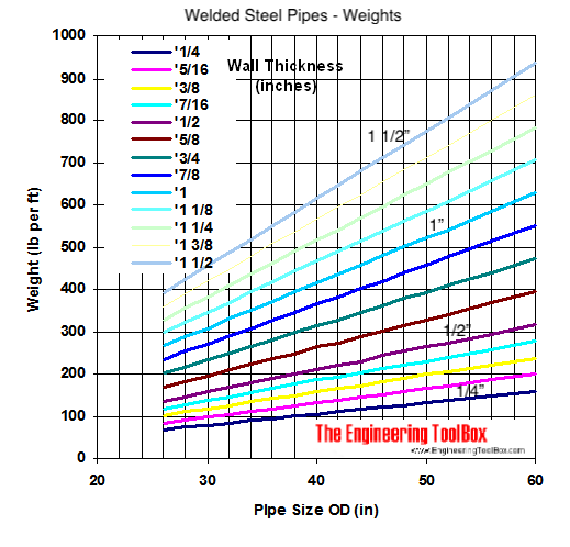
Engineering reference data for the weight of large-diameter welded steel pipes, covering nominal sizes from 26 to 60 inches with wall thicknesses from 1/4 to 1 1/2 inches. Understanding pipe weight is critical for structural support design, transportation planning, and installation handling.
Weights of welded steel pipes ranging size 26 - 60 inches with wall thickness 1/4 to 1 1/2:
Key Formulas
The weight per unit length of a pipe is determined by its cross-sectional area and material density.
Pipe Weight per Unit Length
Where the inner diameter (D_i) is calculated from the outer diameter (D_o) and wall thickness (t):
Alternate Form Using Wall Thickness
This form substitutes (D_i) directly:
Variables
| Symbol | Description | Unit |
|---|---|---|
| (W) | Weight per unit length | lb/ft |
| (D_o) | Outside diameter | in |
| (D_i) | Inside diameter | in |
| (t) | Wall thickness | in |
| (\rho) | Material density (for carbon steel, ~490 lb/ft³) | lb/ft³ |
Pipe Weight Reference Data
Nominal Size(in) | Outside Diameter(in) | Wall Thickness(in) | Weight per Foot(lb/ft) |
|---|---|---|---|
| 26 | 26 | 0.25 | 68.77 |
| 30 | 30 | 0.3125 | 98.05 |
| 36 | 36 | 0.375 | 142.43 |
| 42 | 42 | 0.5 | 223.73 |
| 48 | 48 | 0.625 | 320.5 |
| 54 | 54 | 0.75 | 433.38 |
| 60 | 60 | 1 | 643.68 |
Source: engineeringtoolbox.com
Unit Converter
Steel Pipe Weight Unit Converter
Weight Trend
The interactive chart below represents the source pipe-size/wall-thickness/weight diagram as plottable values.
Pipe Weight vs. Nominal Size
Original Pipe Weight Diagram
The original source diagram is preserved and represented by the interactive weight trend above.
Source Table Note
The cached source page includes a non-engineering layout/search table in addition to the pipe-weight diagram. For strict source-table preservation, the detected UI/search rows are reproduced below; they are not steel-pipe weight data.
Cell 1 | Cell 2 | Cell 3 | Cell 4 | Cell 5 |
|---|---|---|---|---|
| × | × | 検索 | ||
| × |
Source: engineeringtoolbox.com
Key Definitions
- Nominal Pipe Size (NPS): A dimensionless number that indicates the approximate pipe size. For NPS 14 and larger, the number corresponds to the outside diameter in inches.
- Wall Thickness (t): The uniform thickness of the pipe shell. For a given NPS, a higher schedule number (e.g., Sch 80) indicates a greater wall thickness and higher pressure rating.
- Schedule: A standardized designation (e.g., Sch 40, Sch XS) that defines the wall thickness for a given nominal pipe size.
Engineering Notes
- Density Variation: The calculated weight uses a standard density for carbon steel (490 lb/ft³). The actual weight can vary with alloy composition and manufacturing tolerances.
- Table Accuracy: The weight values in the reference table are for standard wall pipes. Weight changes non-linearly with wall thickness due to the changing circumference.
- Handling & Support: Total pipe weight (length × weight/ft) is critical for calculating loads on supports, cranes, and transport vehicles. Include allowances for fittings, flanges, and internal fluid weight in final design.
- Dimensional Tolerances: Outer diameter and wall thickness have specified manufacturing tolerances (e.g., per ASTM A135, ASTM A139). These tolerances affect the calculated weight.