
Wire Gauges
Reference data and engineering information about wire gauges for electrical applications.
Overview
The American Wire Gauge (AWG) system—also known as Brown and Sharpe (B&S) Wire Gauge—is the standard method for denoting wire diameter in North America. Gauge numbers are assigned to the bare conductor diameter with insulation removed. A higher AWG number corresponds to a thinner wire: typical household wiring uses AWG 12 or 14, while telephone wire commonly uses AWG 22, 24, or 26.
Because of the small air gaps between strands, a stranded wire with the same current-carrying capacity and resistance as a solid conductor will always have a slightly larger overall diameter. The tables below cover single, solid, round conductors unless otherwise noted.
Key Formulas
Resistance per length
Where is the conductor resistivity, is the length, and is the cross-sectional area.
Voltage drop (single-phase, one-way run)
Current derating for elevated ambient temperature
Where is the temperature correction factor from the table below.
Variables
| Symbol | Description | Unit |
|---|---|---|
| Electrical resistance | Ω | |
| Electrical resistivity | Ω·m | |
| Conductor length | m | |
| Cross-sectional area | mm² | |
| Current | A | |
| Voltage drop | V | |
| Temperature correction factor | — |
AWG Dimensions and Resistance
AWG | Diameter(mm) | Cross Section(mm²) | Resistance Cu(Ω/1000m) | Resistance Al(Ω/1000m) |
|---|---|---|---|---|
| 40 | 0.08 | 0.005 | 3448 | 5300 |
| 36 | 0.13 | 0.013 | 1326 | 2038 |
| 32 | 0.2 | 0.031 | 556 | 855 |
| 28 | 0.33 | 0.08 | 216 | 331 |
| 26 | 0.41 | 0.13 | 133 | 204 |
| 24 | 0.51 | 0.2 | 88 | 133 |
| 22 | 0.64 | 0.33 | 54.3 | 83.4 |
| 20 | 0.81 | 0.52 | 33.9 | 52.1 |
| 18 | 1.02 | 0.82 | 21.4 | 32.9 |
| 16 | 1.29 | 1.31 | 13.5 | 20.7 |
| 14 | 1.63 | 2.08 | 8.45 | 13 |
| 12 | 2.05 | 3.31 | 5.31 | 8.17 |
| 10 | 2.59 | 5.26 | 3.34 | 5.13 |
| 8 | 3.26 | 8.37 | 2.1 | 3.23 |
| 6 | 4.11 | 13.3 | 1.32 | 2.03 |
| 4 | 5.19 | 21.2 | 0.83 | 1.27 |
Source: engineeringtoolbox.com
AWG Diameter and Cross-Section Area
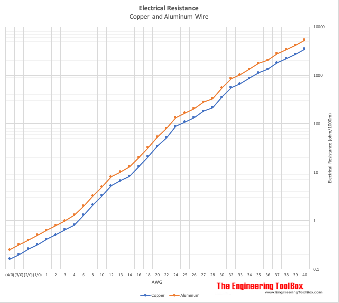
Copper and Aluminum Wire Resistance by AWG
Current Ratings — PVC-Insulated Copper Cable
Current ratings below apply to PVC-insulated single and multicore wiring cables at ambient temperature up to 30 °C and voltage up to 1000 V. Actual capacity depends on installation method, enclosure, conductor temperature, and ambient conditions.
AWG | Cross Section(mm²) | Single Core(A) | Multicore ≤3(A) | Multicore 4-6(A) |
|---|---|---|---|---|
| 24 | 0.2 | 3.5 | 2 | 1.5 |
| 22 | 0.33 | 5 | 3.5 | 2.5 |
| 20 | 0.52 | 7 | 5 | 3.5 |
| 18 | 0.82 | 10 | 7 | 5 |
| 16 | 1.31 | 15 | 10 | 7 |
| 14 | 2.08 | 20 | 15 | 10 |
| 12 | 3.31 | 25 | 20 | 15 |
| 10 | 5.26 | 35 | 25 | 20 |
| 8 | 8.37 | 50 | 35 | 25 |
| 6 | 13.3 | 70 | 50 | 35 |
| 4 | 21.2 | 95 | 70 | 50 |
Source: engineeringtoolbox.com
Temperature Correction Factors
When ambient temperature exceeds 30 °C, multiply the rated current by the applicable correction factor.
Ambient Temperature | Correction Factor |
|---|---|
| 31 – 40 °C | 0.82 |
| 41 – 45 °C | 0.71 |
| 45 – 50 °C | 0.58 |
Source: engineeringtoolbox.com
AWG Resistance Calculator
Wire Resistance
Voltage Drop (Single Phase DC)
Unit Converter
Wire Gauge Unit Converter
Restored Original Source Tables
The following tables are restored from the original source page to preserve the complete reference data.
AWG - American Wire Gauge Current Ratings
Single Core | Multicore | Multicore | Multicore | Multicore | Multicore | Typical Max. Current Load Ratings - Copper (amps) 1) | Typical Max. Current Load Ratings - Copper (amps) 1) | Typical Max. Current Load Ratings - Copper (amps) 1) | Typical Max. Current Load Ratings - Copper (amps) 1) | Typical Max. Current Load Ratings - Copper (amps) 1) | Typical Max. Current Load Ratings - Copper (amps) 1) |
|---|---|---|---|---|---|---|---|---|---|---|---|
| up to 3 cores | 4 - 6 cores | 7 - 24 cores | 25 - 42 cores | 43 and above | |||||||
| 40 | 0.08 | . | 0.005 | 3448 | 5300 | ||||||
| 39 | 0.09 | . | 0.0064 | 2693 | 4141 | ||||||
| 38 | 0.1 | 0.004 | 0.0078 | 2210 | 3397 | ||||||
| 37 | 0.11 | 0.0045 | 0.0095 | 1810 | 2789 | ||||||
| 36 | 0.13 | 0.005 | 0.013 | 1326 | 2038 | ||||||
| 35 | 0.14 | 0.0056 | 0.015 | 1120 | 1767 | ||||||
| 34 | 0.16 | 0.0063 | 0.02 | 862 | 1325 | ||||||
| 33 | 0.18 | 0.0071 | 0.026 | 663 | 1019 | ||||||
| 32 | 0.2 | 0.008 | 0.031 | 556 | 855 | ||||||
| 30 | 0.25 | 0.01 | 0.049 | 352 | 541 | ||||||
| 28 | 0.33 | 0.013 | 0.08 | 216 | 331 | ||||||
| 27 | 0.36 | 0.014 | 0.096 | 180 | 276 | ||||||
| 26 | 0.41 | 0.016 | 0.13 | 133 | 204 | ||||||
| 25 | 0.45 | 0.018 | 0.16 | 108 | 166 | ||||||
| 24 | 0.51 | 0.02 | 0.2 | 88 | 133 | 3.5 | 2 | 1.6 | 1.4 | 1.2 | 1 |
| 22 | 0.64 | 0.025 | 0.33 | 52 | 80 | 5 | 3 | 2.4 | 2.1 | 1.8 | 1.5 |
| 20 | 0.81 | 0.032 | 0.5 | 34 | 53 | 6 | 5 | 4 | 3.5 | 3 | 2.5 |
| 18 | 1 | 0.04 | 0.82 | 21 | 32 | 9.5 | 7 | 5.6 | 4.9 | 4.2 | 3.5 |
| 16 | 1.3 | 0.051 | 1.3 | 13 | 20 | 15 | 10 | 8 | 7 | 6 | 5 |
| 14 | 1.6 | 0.064 | 2.1 | 8.2 | 13 | 24 | 15 | 12 | 10 | 9 | 7.5 |
| 13 | 1.8 | 0.072 | 2.6 | 6.6 | 10 | ||||||
| 12 | 2.1 | 0.081 | 3.3 | 5.2 | 8 | 34 | 20 | 16 | 14 | 12 | 10 |
| 10 | 2.6 | 0.1 | 5.3 | 3.3 | 5 | 52 | 30 | 24 | 21 | 18 | 15 |
| 8 | 3.3 | 0.13 | 8.3 | 2.1 | 3.2 | 75 | 40 | 32 | 28 | 24 | 20 |
| 6 | 4.1 | 0.17 | 13.3 | 1.3 | 2 | 95 | 55 | 44 | 38 | 33 | 27 |
| 4 | 5.2 | 0.2 | 21.2 | 0.81 | 1.3 | 120 | 70 | 56 | 49 | 42 | 35 |
| 3 | 26.7 | 0.65 | 0.99 | 154 | 80 | 64 | 56 | 48 | 40 | ||
| 2 | 6.5 | 0.26 | 33.6 | 0.51 | 0.79 | 170 | 95 | 76 | 66 | 57 | 57 |
| 1 | 7.4 | 0.29 | 42.4 | 0.41 | 0.63 | 180 | 110 | 88 | 77 | 66 | 55 |
| 0 (1/0) | 8.3 | 0.33 | 53.5 | 0.32 | 0.5 | 200 | |||||
| 00 (2/0) | 9.3 | 0.37 | 67.4 | 0.26 | 0.39 | 225 | |||||
| 000 (3/0) | 10.4 | 0.41 | 85 | 0.2 | 0.32 | 275 | |||||
| 0000 (4/0) | 11.7 | 0.46 | 107 | 0.16 | 0.25 | 325 | |||||
| 250 | 127 | 345 | |||||||||
| 300 | 152 | 390 | |||||||||
| 400 | 178 | 415 |
Source: engineeringtoolbox.com
Original Source Images
The following original source images are preserved to avoid losing visual reference material. When an image contains chart or tabular data, its extracted values are represented in the page tables, calculators, or interactive charts; remaining images are retained as visual source references.
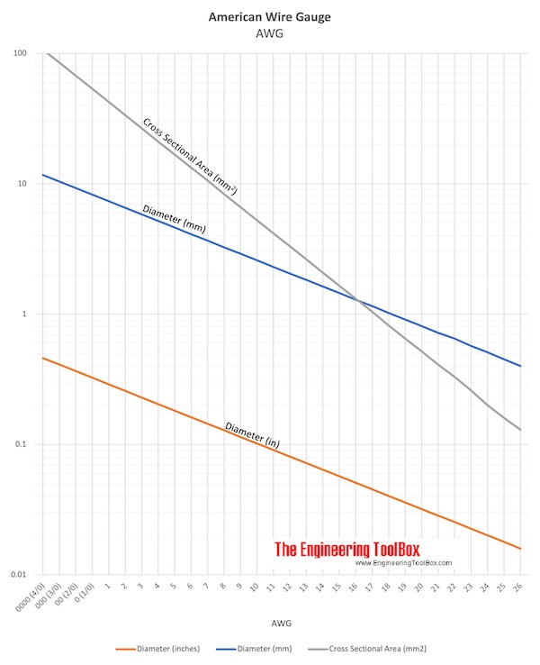 American Wire Gauge - AWG
Engineering Notes
- Stranded vs. solid conductors. A stranded wire that matches the resistance and ampacity of a solid conductor will have a slightly larger outside diameter due to interstitial air space.
- Longer runs require larger wire. To limit voltage drop on long circuits, reduce the AWG number (increase conductor area). A common engineering guideline is to keep voltage drop under 3% for branch circuits and 5% total (feeder plus branch).
- Bundled conductors. When multiple current-carrying conductors share a conduit or bundle, additional derating beyond the temperature factors above is required per NEC/NFPA 70 or local codes.
- Aluminum conductors. Aluminum wire carries roughly 61% of the current capacity of equivalent copper due to its higher resistivity (2.65 × 10⁻⁸ Ω·m vs. 1.724 × 10⁻⁸ Ω·m). Contact resistance at termination points is also higher, requiring special connectors.
- Always consult manufacturer data. Ratings vary with insulation type (PVC, XLPE, EPR), conductor temperature rating, and installation method. The values here are typical reference figures only.